
PCB Laser Marking Machines for Electronics, New Energy, and Medical Device Manufacturing
Unreadable codes, failed audits, and substrate damage from mismatched laser types cost electronics manufacturers weeks of rework and delayed shipments. When traceability requirements tighten across automotive, medical, and new energy supply chains, the marking system becomes a pass-or-fail checkpoint — not an afterthought.
We design and deliver industrial-grade PCB laser marking machines for mid-to-large-scale manufacturers who need microcode precision on demanding substrates, verified compliance marking, and direct integration into SMT production lines. Our scope covers process consultation, laser type selection, custom machine configuration, inline or offline deployment, and post-installation validation — from initial substrate testing through production sign-off.
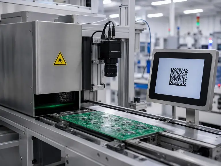
Marking Precision and Substrate Coverage
for Industrial PCB Applications
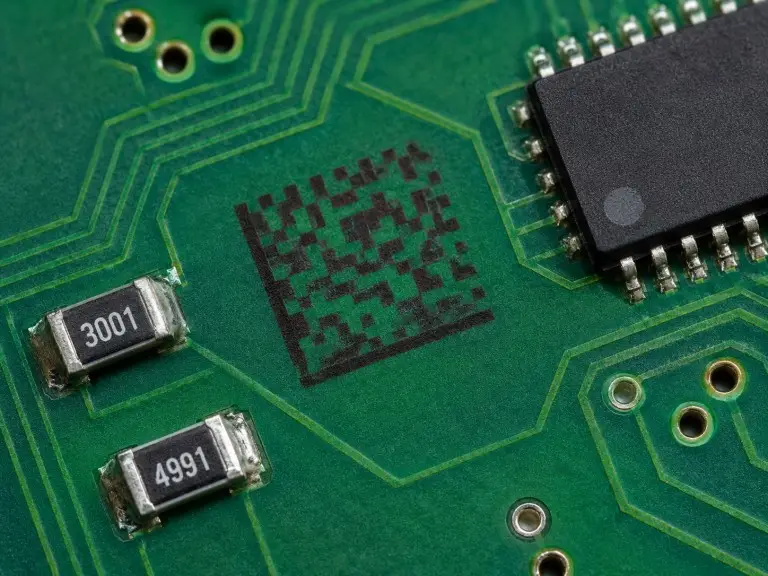
Our PCB laser marking systems achieve microcode marking precision of up to 0.02mm and multi-material vision-based positioning accuracy of ±0.005mm under controlled conditions, supporting character sizes and code densities that standard marking equipment cannot reliably produce. These precision levels apply to manufacturers working with FR4, white and colored solder mask, flexible FPC, and metal-core substrates where marking contrast and readability must survive reflow, wave soldering, and cleaning processes.
We configure each system around the specific substrate and code requirements of the application. UV lasers (355nm) are the primary choice for heat-sensitive substrates and white solder mask boards, where cold processing avoids thermal damage to adjacent components. Green lasers (532nm) serve applications on copper and certain metallic substrates requiring high contrast without surface deformation. Fiber lasers (1064nm) handle bare FR4, metal-core boards, and applications where marking speed takes priority over minimal heat-affected zone control. CO2 lasers apply to specific organic coating and solder mask marking scenarios where wavelength absorption characteristics favor longer-wavelength processing.
Microcode Precision
Character sizes and code densities that standard marking equipment cannot reliably produce.
Vision Positioning
CCD fiducial mark identification compensates for panel-level alignment variation.
Multi-Substrate
FR4, white and colored solder mask, flexible FPC, and metal-core substrates all supported.
Post-Process Durability
Readability validated through reflow, wave soldering, and cleaning processes.
Substrate–Laser Pairing Recommendations
The following table summarizes the primary substrate-laser pairings we recommend during scoping. Final laser selection depends on board-level testing with your actual production panels, since solder mask color, thickness, and supplier formulation influence marking contrast and durability.
| Laser Type | Primary PCB Substrates | Typical Use Case | Key Consideration |
|---|---|---|---|
| UV (355nm) | White/colored solder mask, FPC, heat-sensitive assemblies | Microcode marking near populated components | Minimal HAZ; preferred when component proximity is ≤1mm |
| Green (532nm) | Copper layers, certain metallic substrates | High-contrast marking on reflective surfaces | Absorption rate varies by surface finish; sample test required |
| Fiber (1064nm) | Bare FR4, metal-core PCB, thick substrates | High-speed marking where thermal budget allows | Wider HAZ than UV; not recommended for thin FPC or populated boards |
| CO₂ (10.6μm) | Organic coatings, specific solder mask types | Legacy marking requirements, larger character sizes | Limited for fine-pitch microcode below 0.3mm character height |
Final laser selection depends on board-level testing with your actual production panels, since solder mask color, thickness, and supplier formulation influence marking contrast and durability.
Common Laser Type Selection Errors
and How to Avoid Them
Choosing the wrong laser type for a given PCB substrate is the most frequent — and most costly — procurement mistake in this equipment category, often resulting in unreadable codes, substrate scorching, or contrast levels that fail scanner verification at downstream stations. We address this during the consultation phase, before any machine configuration begins.
Assuming Fiber Lasers Work Across All PCB Materials
When manufacturers assume that fiber lasers work across all PCB materials without confirming substrate-specific absorption characteristics, the marking often produces low-contrast codes on white solder mask or causes micro-cracking on flexible FPC. We see this pattern frequently in projects where the initial equipment specification was based on general laser marking experience rather than PCB-specific testing.
Misjudging Solder Mask Color Impact on Readability
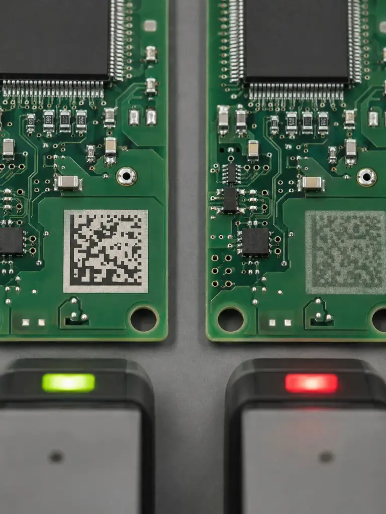
Red and dark green substrates behave differently under the same laser wavelength, and scanner readability depends on the contrast ratio between the marked area and surrounding board color. A mark that appears legible to the eye can still fail automated line scanners operating at production speed.
Inline and Offline Deployment
for SMT Production Lines
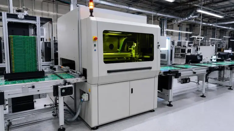
Our PCB laser marking machines deploy in both inline configurations — integrated directly into the SMT production flow — and offline standalone stations for batch processing, prototyping, or secondary marking operations. Inline deployment is the standard approach for manufacturers running continuous SMT lines where every board requires a unique traceability code before entering the solder paste printing stage.
Inline Integration
Integrated directly into the SMT production flow — every board receives a unique traceability code before entering solder paste printing.
- SMEMA and IPC-Hermes 9852 communication protocol support for upstream/downstream synchronization without custom middleware
- CCD vision positioning identifies fiducial marks on each board to compensate for panel-level alignment variation
- ±0.005mm positioning accuracy for marking within tight keep-out zones on densely populated boards
- Post-mark verification via integrated code reader — boards that fail are flagged before exiting the station
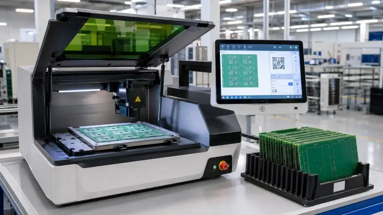
Offline Standalone
Batch processing, prototyping, or secondary marking operations — no line disruption required for deployment.
- Independent operation for batch processing without impacting production line uptime
- Flexible solution for prototyping and sample marking during consultation phase
- Secondary marking operations — rework boards, additional codes, supplementary identifiers
- Same precision and verification standards as inline systems
- Upgradeable to inline integration configuration when production requirements evolve
MES and ERP Integration
MES and ERP integration follows a standard data flow: the host system sends marking content (serial number, lot code, work order identifier) to the marking station before the board arrives; the system marks and verifies; verification results (pass/fail, timestamp, board ID) report back to the MES for traceability records.
We configure the communication interface during the integration phase, and the specific protocol (Ethernet/IP, OPC-UA, serial, or custom API) depends on the factory's existing MES architecture and should be confirmed during scoping.
Post-mark verification is handled by an integrated code reader that grades each mark against the application's readability threshold before the board exits the station. Boards that fail verification are flagged for rerouting or rejection, preventing unreadable codes from entering downstream processes.
Target Industries, Compliance Requirements,
and Applicability Boundaries
Our PCB laser marking systems serve manufacturers in three primary verticals — electronics (EMS/OEM contract manufacturers), new energy (battery management systems, power conversion modules), and medical devices — where regulatory traceability is a procurement prerequisite rather than an optional feature. The compliance framework governing each vertical determines the marking content, code format, and verification requirements that the system must support.
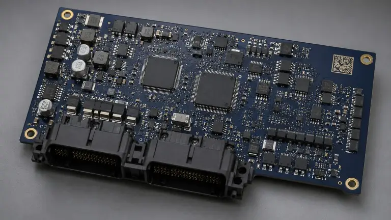
Automotive Electronics
For automotive electronics supply chains operating under IATF 16949, every PCB in an ECU, sensor module, or control unit must carry a unique identifier traceable across the full production lifecycle. We configure DataMatrix and QR code formats that meet the data density and redundancy requirements specified by OEM audit checklists.
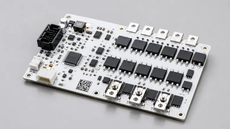
New Energy
Battery management systems (BMS) and power conversion modules require traceable marking across the full supply chain. Critical energy electronics components must maintain verifiable identification throughout manufacturing, assembly, and field deployment.
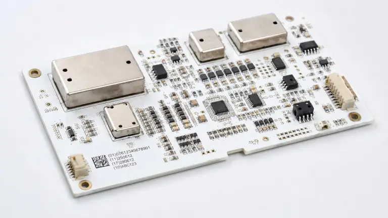
Medical Devices
For medical device manufacturers subject to ISO 13485 and FDA UDI requirements, the marking system must produce codes that remain legible after sterilization, conformal coating, and long-term storage — conditions we validate through accelerated aging and readability testing during the sample approval stage.
Applicability Boundaries
This service is designed for industrial-grade PCB traceability applications. We do not configure systems for general-purpose engraving on non-PCB materials (wood, leather, acrylic), consumer product labeling, or decorative marking. Manufacturers whose marking requirements fall outside PCB substrates and industrial traceability standards should evaluate general-purpose laser marking equipment instead.
From Consultation to
Production Line Sign-Off
Each engagement begins with a technical consultation where we align on substrate types, code specifications, line speed requirements, and compliance framework before proposing a machine configuration. We provide sample marking on the customer's actual production boards as the first validation gate — no configuration is finalized without confirmed marking quality on representative substrates.
Application Consultation & Substrate-Laser Compatibility Assessment
Align on substrate types, code specifications, line speed requirements, and compliance framework before proposing a machine configuration.
Sample Marking & Code Readability Verification
Sample marking on the customer's actual production boards. No configuration is finalized without confirmed marking quality on representative substrates.
Custom Machine Configuration
Laser type, vision system, conveyor, and communication interfaces — all configured based on validated results from the first two stages.
Factory Acceptance Testing & On-Site Installation
Factory acceptance testing at our facility in Suzhou, followed by on-site installation and line integration.
Production Validation & Post-Installation Support
Production validation, operator training, and post-installation technical support to ensure stable system operation in your production environment.
Delivery timelines depend on configuration complexity, integration scope (inline vs. offline, single-station vs. multi-station), and any custom mechanical or software requirements. Standard configurations with no custom integration typically ship faster than systems requiring MES protocol development or non-standard conveyor dimensions. Specific timelines should be confirmed during the scoping phase.
FAQ
The correct laser type depends on your substrate material, solder mask color, component proximity, and required character size. We conduct sample marking on your actual production boards during the consultation phase to validate contrast, readability, and thermal impact before recommending a final configuration.
Most factory MES platforms connect through standard protocols (Ethernet/IP, OPC-UA, serial). Whether custom interface development is needed depends on your MES vendor, data format requirements, and the specific traceability fields your system expects. We confirm integration scope during the technical consultation.
We support DataMatrix (ECC200), QR Code, Code 128, and other 1D/2D formats. The specific format, data content, and error correction level should align with your OEM or regulatory audit checklist — requirements that vary by customer and should be defined before configuration.
Yes. An integrated code reader grades each mark immediately after printing. Boards that fail the readability threshold are flagged before leaving the station. The verification grading standard (ISO/IEC 15415 or customer-specific) is configured during setup.
Lead time depends on laser type, vision system options, conveyor specifications, and integration complexity. We provide a confirmed timeline after the scoping call once configuration details and integration requirements are defined.
Next Steps — Start a Technical Evaluation
The right PCB laser marking configuration depends on a short list of variables: your substrate materials and solder mask types, the code format and density your compliance framework requires, your line speed and throughput targets, and whether the system integrates inline or operates as a standalone station. These variables determine laser type, vision system configuration, communication protocol, and mechanical layout — none of which should be assumed before testing.
In our experience delivering marking systems across electronics, medical device, and new energy manufacturing environments, the engagements that reach production validation fastest are those where substrate samples and compliance documentation are available at the consultation stage. When these inputs arrive late, the scoping and sample approval phases extend, which delays the configuration freeze and pushes the overall delivery timeline. We structure our process to surface these dependencies early, so that laser selection, integration planning, and factory acceptance testing proceed without backtracking.
To start a technical evaluation, share your board specifications (substrate type, solder mask color, board dimensions, panel format), marking requirements (code format, character size, content fields), compliance framework (IATF 16949, ISO 13485, FDA UDI, or OEM-specific), and current line configuration (SMEMA/Hermes compatibility, MES platform, throughput target). Our application engineering team will schedule a scoping call and arrange sample marking on your production boards.